As a long time embedded programmer, I love new chips and dev boards for them. A year or so ago, Ralph Doncaster got me interested in the WinChip CH55x family of microcontrollers. Deqing Sun developed an Arduino IDE compatability library for them. I ordered up some dev boards and started to enjoy the CH552.
The dev boards I found had two rows of pins on 0.6" centers. Which isn’t very breadboard friendly. The center rows of a breadboard are spaced at 0.3", so a 0.6" device wastes three rows of connections. Considering that there are only 5 contacts per column, that means you have two usable contacts on one side and three on the other. So, I decided to design a board that was more friendly to breadboard use.
I’ve designed a few boards before, so I’m not new to the process, but all of those projects were part of a team effort where I had people looking over my shoulder to find errors. I no longer have an Eagle CAD license, so I can’t design boards for commercial use (and you never know if you’ll end up wanting to do that) anymore with it, so I had to learn something else. I ended up with KiCad and dove into designing a new board. Since it was my first time solo and with a new design software, I wanted to keep it easy, so I decided to use mostly through hole parts–just the chip itself and the micro-USB socket were SMT and the socket isn’t really.
Fortunately, this chip can run without any external support parts other than power decoupling caps, so the minimal system is trivial. So, I decided to add a few LEDs. The most important part of the design was the single row of contacts along one side to which a row of pins could be soldered and inserted into one side of a breadboard.
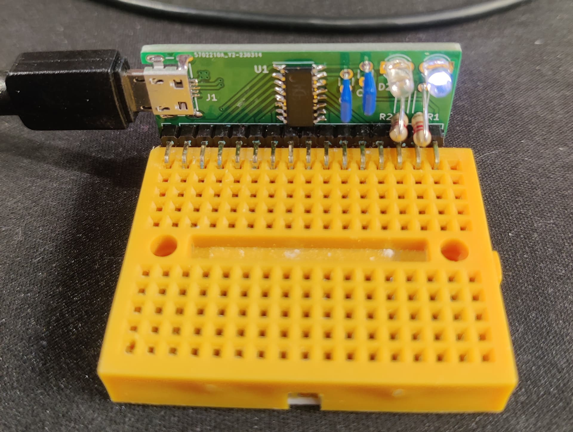
Since it only has 16 pins (one for one corresponding to the pins on the chip from left to right), it fits perfectly on the smallest size of breadboard. I programmed it up and everything worked perfectly the first time! I think I need to make a github page for the design and put it under a proper open hardware license just in case anyone else wants to use it.
I had the boards fabbed by the usual suspect: JLCPCB. They didn’t sponsor me, I bought the boards on my own, but I did pick them based on all the positive press I’ve heard from various youtube personalities. I have to say that I’m blown away by how easy there were to work with and how cheap and fast they are. Admittedly, I have designed boards before and prepared all the files need to fab them before, so this wasn’t a fair test of a completely naive customer, but the process is very well automated. The thing that threw me the hardest was the price. I got 30 boards with international shipping for less than $10(US)! I picked all the cheap options for the board and for shipping, so I was prepared to wait a while for them to arrive, but I ordered on the 16th of March and they just arrived today (March 24). I’m trying very hard not to use too many exclamation points so that the style bot doesn’t get mad at me, but it’s not easy.
Here’s an image of the bare board. The only ‘fancy’ thing I did was use a cutout for the micro-USB connector as it sits ‘inside’ the board thickness.
